

Before when someone had a problem with a Light Emitting Diode (LED) circuit I'd start by asking if they were treating like a light bulb. Now, with light bulbs being made with LEDs I'd have to be more specific. "Are you treating it like an incandescent light bulb?" (About mains {120VAC or 220VAC} LED bulbs later.)
An incandescent light makes light getting a wire really hot. An LED uses electric voltage to separate electrons from their atoms, when an electron "falls" back to orbit a nucleus a photon of light is emitted. The color of the photons depends on the vacant orbit they "fall" into. To make different color LEDs the silicon is mixed with different elements cause particular orbits to be vacated. So LEDs operate on DC of the correct polarity. While incandescent bulbs can be heated by AC or DC, and produce photons of many colors. If hot enough the resulting light is white (a mixture of colors. (About white LEDs, also later.)
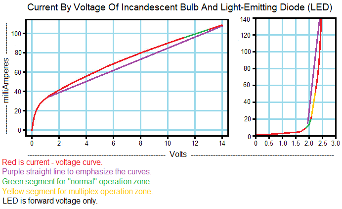
A difference is how incandescents and LEDs respond to voltage. The
graphs in Figure 1 show that in incandescents the current icreases as voltage
increases (no surprise), but the current increases more slowly as voltage
increases. The curve approaches horizontal. This is because the filament's
resistance increases with temperature. It makes them somewhat self-regulating.
(Of course they will burn-out with too much overvoltage.) On the other hand,
the current through an LED increases rapidly for very small increases in
voltage. The curve approaches vertical. Even momentary application of voltage
without current limiting can destroy an LED.
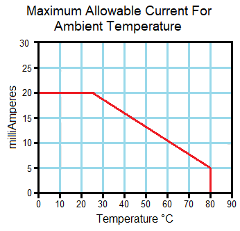
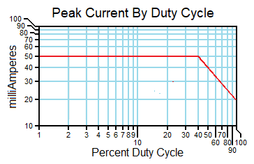
All that is needed to calculate a current limiting resistor is the current of the LED, forward voltage drop, and the supply voltage. For example, a RED indicator driven by a 5V logic circuit. The LED selected has a forward voltage drop of 1.8 V, and maximum continuous current of 20 mA. 25 °C is cool (77 °F) and the device needs to operate in summer. The leads of an LED are the main sink for the bit of heat created and they will (most likely) be inside an encloseure. A very warm day of 100 °F (hot to me! 😀 ) is 37.77 °C. Add a couple degrees for being in an enclosure gives 40 °C. From the example graph at Figure 2, we find the current limit is 16 mA. For a warmer enclosure get the maximum current from graph for the LED you are using. If full brightness is not needed, going lower is okay.
LED agaist "run-away" current caused
by LED temperature variations.". . . However, at constant
voltages VF will drop as the temperature rises, causing an increase in
current."1
The resistor value is then:
5 V - 1.8 V = 3.2 V
3.2 V ÷ 0.016 A = 200 Ω, value resistor
3.2 V × 0.016 A = 0.0512 W, 1/8 W axial or 1/10 W SMD power rated resistor
allows similar derating. If the resistance for RLIMIT dos not work
out to a standard value, use the standard value is larger. For a single LED that's it.
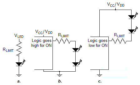
Sometimes the supply voltage for the LED must be calculated. Could be multiple LEDs in series or a low logic supply voltage. The next example is a blue LED driven by 3.3 V logic. 3.8 V forward voltage LED will not work, and the resistor will not protect a 3.2 V The added components make it "Less Simple".
"Less simple" includes needing a higher voltage than part of a circuit can handle, or a higher current, or both. Drive Circuits 1 and 3 in Figure 3 are for logic circuits whose output goes high to turn on the LED(s). Drive Circuits 2 and 4 for outputs that go low to turn on the LED(s). The maximum VLED for the transistors suggested here is 35 V.
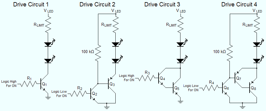
Depending on IC high or low output; for LED current upto ~120 mA
Q1 or Q2 can be 2N3904, with Q3 a 2N3906.
From ~120 mA ~500 mA Q1 can be 2N2222, Q2 a
2N3904, Q3 a 2N2907. Above about 500 mA to about 2.5 A
Drive Circuits 3 or 4 are used because high current bipolar transistors have
lower gain. In fact switching to
FETs (Field Effect Transistors) should be considered. To finish here, the
suggestion for Q4 is 2N2222, Q5 TIP31, Q6
2N3904, Q7 2N2907, Q8 TIP32. The 2N3904, 2N3906, 2N2222
and 2N2907 are old but hard to beat, and inexpensive. TIP31 and TIP32 are old,
have poor gain, but good enough for this.
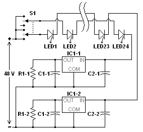
Here is the schematic of a lamp I built on a plastic clothes hanger. It used white, 5 mm, 20 mA LEDs, then covered with OD green para cord. It was ugly and not very bright, but was made so I could see my computer keyboard in my quarters in Afghanistan. The clever bit (IMO) is using an inexpensive LDO (Low DropOut) voltage regulatior IC as a current regulator. With a fixed resistor as the load for a regulated voltage, the current of the IC's input is regulated. The current of the IC's common terminal is at least one thousand times smaller than the output. With active regulation, the 130% overhead of resistive current limiting does not apply. The lowest voltage regulator I could get then was 1.2 V.
To have as many LEDs in series as possible I choose 48 V for the supply. 48 V is considered the highest "safe" voltage, so got a switching mode "wall wart". Some calculations:
3.8 V per LED x 12 LEDs = 45.6 V
48 V - 45.6 V - 1.2 V = 1.2 V. Enough for an LDO to
operate on.
1.2 V ÷ 0.018 mA = 66.66 Ω. Higher standard resistance is
68.1 Ω, 1% tolerance.
1.2 V ÷ 68.1 Ω = 0.0176 mA
1.2 V × 0.0176 mA = 0.02112 W. 1/20 W axial or SMD, or
larger, can be used.
A member of an electronics forum pointed out that the maximum input voltage for
the regulator I used was 35 , while the supply is 48 . That is true,
but several LEDs would have to fail to short for the regulater to be exposed to
more than 35 V. LED shorting is mostly caused by over-heating.
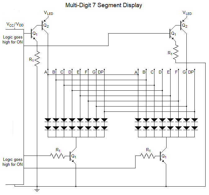
So far have been "low side" driver circuits. So called because the load (LED(s) in this case) is connected to the supply ("high"), and common (the "low") is through the drive device. "High side" drive is useful when the load is connected directly to common. For example, in vehicles. Also for multi-digit seven segment displays and matrix LED displays (next section).
The note on hand drawn circuit diagram should read "In case you need a 220 Volts mains input, you can use up to 90 LEDs in the LED bulb.", to maintain the distinction between individual LEDs and bulb which uses LEDs as the light source with other components.
Created on 20 March 2023
| To Domain Home. | To Dale's Notebook index.
| To Circuits index.
|